KWIKSET manufacturer gets handle on scrap to boost productivity
Written By: Kate Bachman, Stamping Journal Magazine

Forming AHSS, stainless, carbon steel without defects
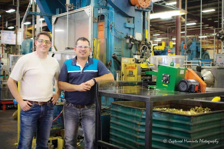
Kwikset’s North American facilities produce 150,000 locksets a day, five days a week—that’s millions of locksets a year. Hinging on all of that production are the stamping operations in which many of the components are formed.
The company’s Denison, Texas, plant manufactures most of the components to supply its North American assembly plants.
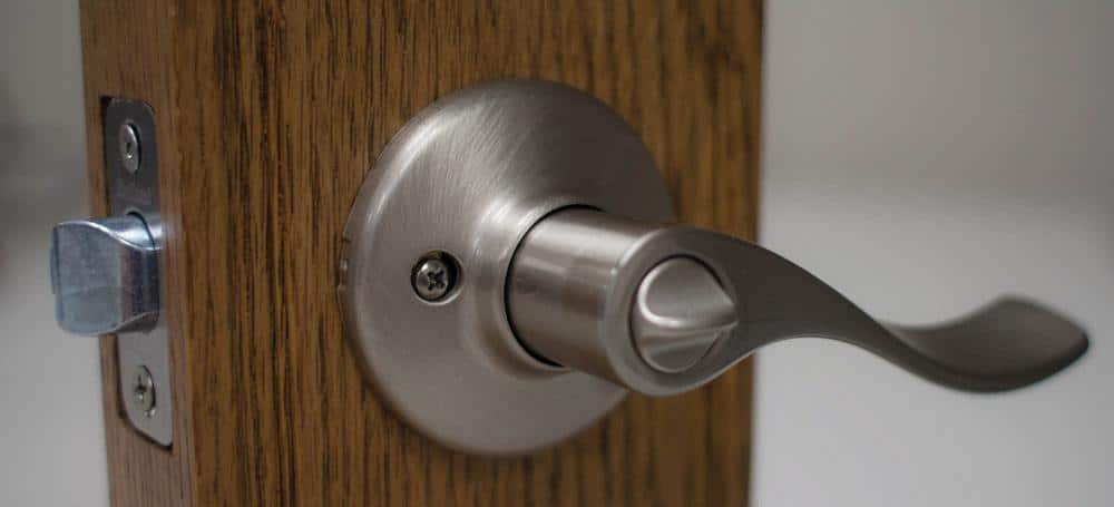
The volume of demand for locksets, handlesets, and doorsets may be a bit mystifying, but considering the number of them in a typical home—front and back doors, garage doors, closet doors—and the growth of urbanization in many parts of the world, apparently they are in high demand in high volumes (see Figure 1).

Kwikset has been securing the world’s homes for decades, and it likely will continue to do so as developing nations continue to build homes with people and household items needing safekeeping.
The Denison Kwikset manufacturing plant has been trying to ramp up to keep pace with demand. “We’re at 91 percent utilization on some of our stamping presses, and we’re just trying to dig ourselves out of the hole,” said Zach Thedford, Kwikset project engineer, who oversees the product stamping operations.
Getting Scrap out of the Way of Speed
When you stamp 2.2 million pieces a day in the manufacture of those lockset and doorset assemblies—550 million stampings a year—smooth, speedy operation is your goal and bottlenecks and obstructions to productivity are your targets.
“Our challenge was to gain higher speed for greater output,” Thedford said. “The limiting factor was the crankshaft-mounted chopper.” The chopper, mounted on a cam attached to a pivot arm, chopped the scrap in an up-and-down motion. The 0.012-inch-thick, 1010 cold-rolled steel material had a tendency to deform.
“After the material has been stamped and formed, the webbing exiting the machine would want to pop up and hang on that blade. Whenever the material was fed into a closed blade, it would fall over itself and create a mess.
“So what we did to counter that is we would only make a progression when that blade was fully open. But that gave us a real small feed window. And that limited how fast we could run the machine. With such a small feed window, I had to run the feeder at high acceleration and velocity just to get a reasonable production rate,” Thedford said.
So because the chopper was mounted on the crankshaft and synchronized with the feeder, the scrap-chopping motion was determining the speed.
“The progression wasn’t tied to the press but the opportunity was tied to the press. So the opportunity to chop wasn’t there until it was at the top of the stroke. And the feed window was small because I had to wait until the blade was fully open,” Thedford explained.
“This line is highly utilized. We had to get more output out of it. That was our first bottleneck of the process.”
Increasing speed could not come at the expense of the material. The final appearance of the consumer product cannot have feeder marks or scratches (see Figure 2).

Scanning Options
Thedford and his team evaluated options.
Modifiy the Cam. They looked at the possibility of putting a new lobe on the machine so that the blade stroke would be longer. “But that would have been expensive, and I didn’t have an engineered solution, so we dismissed that idea,” he said.
The team also considered substituting a motorized chopper for the crank-mounted one. “But a conventional motorized chopper doesn’t work for our application, because motorized orbital choppers work on the same concept as the pivot arm, except a motor drives it instead of the press driving it. The fastest speed I could get out of that system was 100 strokes per minute [SPM],” Thedford said.
In addition, Thedford was concerned that if the thin material progressed while the blades were closed, it would buckle. “We use those same choppers in other areas of our department, and we have to build in slack to compensate whenever it feeds into a closed blade. Those presses run at 40 SPM, so it’s not really a big deal, but when you’re going 100 SPM and you’ve got a 3-inch. progression, you can really create a mess if the blade hits two times in a row.”
Another complication was with the positioning of the chopper. A motorized chopper is engineered to sit on the floor below the passline, Thedford explained. “So that works fine if you have an underground scrap conveyor system. But for us, all of our scrap goes into containers. We struggled with how we’d get a motorized chopper high enough so that our container could fit underneath it, but at the same time, be able to feed the material into it, because it feeds at the top of the equipment. We’d have to have a weird tall loop going down into our equipment to be able to put it into a scrap container. We’d have to raise the whole press in the air, which would be expensive … I know, because I’ve done it!”
Who You Gonna Call? Scrap Busters
At that point, Thedford researched other technologies and OEMs that make scrap processing equipment, including Sweed Machinery. The OEM makes scrap machinery not only for stampers and manufacturers generating scrap in their production, but also for scrap recycling companies that process scrap on a large scale.
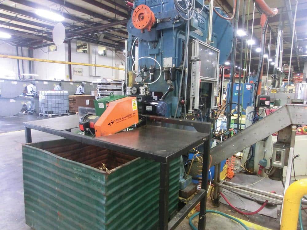
In collaboration with Sweed’s engineers, Thedford and his team modified a motorized rotary chopper model, 450 AM, that had been used for cutting metal banding to work in their press application (see Figure 3).

The way that this unit works for recyclers is that the feed system grabs the metal banding and pulls it into the blades and chops it up into small pieces. Working with Sweed, we removed that feed system and we just use our press’s pull feed to act like that feed system. So our pull feeder on the press drives the material into the blades.”
Rotary Chopper Fits the Slot. The rotary chopper has two blades—a stationary blade and one that spins around on an axis like a wheel to chop the metal, Thedford explained. “As you introduce material, it cuts the strip, but it’s moving so fast that you don’t even see it. It has only one blade but it spins at a high RPM [revolutions per minute] and it’s closed for only a fraction of a second, so you don’t have problems with material feeding into a closed blade.
“So that is our solution.”
Sweed engineers worked through velocity and acceleration calculations to determine how fast the machine and press can run before problems occur. That calculation is up to 225 cycles a minute.
Mounting System Aligns. Another favorable aspect of the situation is the position of the machine in relation to the press.
“Another reason the rotary scrap chopper fits our application is how it can be mounted into the system. Sweed made us a stand to put on the same passline as the material.”
Not All Smooth Sliding Yet
Kwikset is still working out some kinks that have dragged speed and resulted in downtime related to integrating a type of scrap processor not originally engineered to attach to a press.
“There’s a limitation on the width of material that the rotary chopper is able to cut with a small-frame unit. I think it’s because what we’re trying to do is new. They’re used to cut real narrow banding. Our material is 31⁄2 inch wide, but my opening is only 3.8 in. wide. So it fits and it goes, but we have tracking problems.”
Thedford said that the uneven feeding that commonly occurs with pull feeds caused by material thickness variations causes problems because the clearance between the 3.5-in. material and the 3.8-in. chute is so small. “If the strip is not tracking straight, it’ll jam in the chute of the chopper. Or if something goofy happens in the webbing—if it wants to move or tear out—you’re hosed because that little finger of the webbing is going to grab onto the side and create a jam.”
In response, Sweed Machinery is re-engineering the small-frame model to widen the chute to accept 6-in.-wide material. Until it is ready, Thedford installed a sensored wire that turns off the press if the material buckles up into the wire; it will shut off the press to avert a jam. They also put in some roller cams to keep everything aligned so the material doesn’t “walk off.”
Because material is fed into the rotary chopper horizontally, it integrates well into the passline with a container underneath it, Thedford reported.
“I only had to raise the press up 8 inches, which is much easier than raising it 3 feet,” he said.
Thedford anticipates that the modified machine with a wider chute will resolve current problems. “We’re still planning on replacing more of our crank and motorized choppers with the new rotary machines, even though we’re having some trouble with them now. I think that the benefit with a wider-chute machine is going to be huge.”
Waiting for the Last Pin to Fall Into Place
When one door opens, another shuts?
Once Thedford and the team resolve the scrap bottleneck problem, they’ll turn their focus to the next bottleneck: downstream operations.
“Even though the press, the feed, and the chopper can run at over 200 cycles a minute, my secondary operation can run only 150 [cycles per minute.] If we were running at 225, we would overload those secondaries,” Thedford said.
“We’ve pretty much eliminated the first bottleneck; now we’ve got new bottlenecks down the line that need to be addressed.”

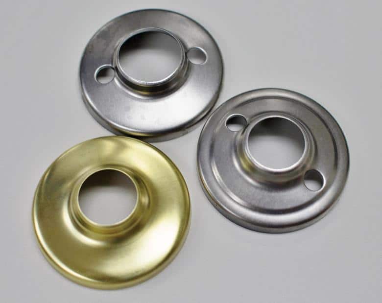
The secondary operation is dimpling. The decorative bezel that goes behind the knob needs a dimple to attach to the steel liner (see Figure 4). Thedford said that the operation cannot be done in the progressive die, so they have to do that in a secondary operation. “We looked at trying to make it into a progressive-die operation, but we could only find one company that came even close and they couldn’t do it at 150 cycles a minute. We were going to get into aero cams and all kinds of craziness,” he said.
“We’re learning through it. We’re going through all the growing pains. Within a few months, we’ll have the kinks worked out. It’s all new, right?”

